La disposición de la cavidad y la superficie de separación del molde.
La disposición de la cavidad y la superficie de separación del molde.
Las piezas conformadas se refieren a las piezas del molde que participan directamente en la formación del espacio de la cavidad, como la matriz de retorno (cavidad), el punzón (núcleo), la pieza, la extracción lateral del núcleo, etc. Al diseñar piezas moldeadas, se debe prestar total atención a la tasa de contracción del moldeo del plástico, la pendiente de desmoldeo y la procesabilidad para la fabricación y el mantenimiento.
El diseño de piezas formadas generalmente se puede realizar en los siguientes pasos
① Determinar el número de cavidades del molde.
② Determine la posición de la cavidad.
③ Determine la línea de separación de la pieza de plástico y la superficie de separación del molde.
④ Cuando se requiera extracción lateral del núcleo, diseñe un mecanismo de extracción lateral del núcleo.
⑤ Determine las dimensiones de formación de la cavidad del núcleo y el ángulo de tiro.
⑥ Determinar la combinación y los métodos de fijación de las piezas formadas.
Fabricante de moho de heces en China (jfmoulds.com)
Determinar el número de cavidades.
Si se ha determinado de antemano la máquina de moldeo por inyección que coincide con el molde, el número de cavidades se puede determinar de las dos formas siguientes
(1) Según el volumen de inyección nominal de la máquina de inyección utilizada
(Peso total de piezas de plástico en cada cavidad + hormigón en el sistema de compuerta) 80% del volumen de inyección nominal de la máquina de inyección.
(2) Según la fuerza de sujeción nominal de la máquina de inyección
Suponiendo que la suma de las áreas proyectadas de cada cavidad y el corredor en la superficie de separación es la parte S (mm²), la fuerza de sujeción nominal de la máquina de inyección es la parte F y la presión promedio del plástico fundido sobre la cavidad es el tipo, entonces
S Cerradura doméstica tipo F x 80%
Uno: alineación de la cavidad
El principio de clasificación.
① El principio del canal de flujo más corto: reducir el material solidificado en el sistema de compuerta y ahorrar el costo de fabricación de acero y moldes.
② Principio de equilibrio de temperatura: asegúrese de que las temperaturas en todas las partes de la cavidad del molde sean aproximadamente iguales para garantizar que las tasas de contracción de las piezas de plástico en cada cavidad sean las mismas.
③ Principio de equilibrio de presión: asegúrese de que la fuerza resultante de la fuerza de tracción que soporta el molde durante la inyección esté cerca del centro del molde y en línea recta con la fuerza de sujeción de la máquina de moldeo por inyección.
④ Principio de equilibrio de alimentación: para moldes con múltiples cavidades en un molde, la misma pieza de plástico debe alimentarse desde la misma posición para garantizar la intercambiabilidad de las piezas de plástico. El tamaño y la longitud de la corredera y de la compuerta deben adaptarse al tamaño de la pieza de plástico, y es necesario garantizar que todas las cavidades se alimenten y llenen simultáneamente en la medida de lo posible.
Precauciones para la disposición de moldes con múltiples cavidades en un solo molde.
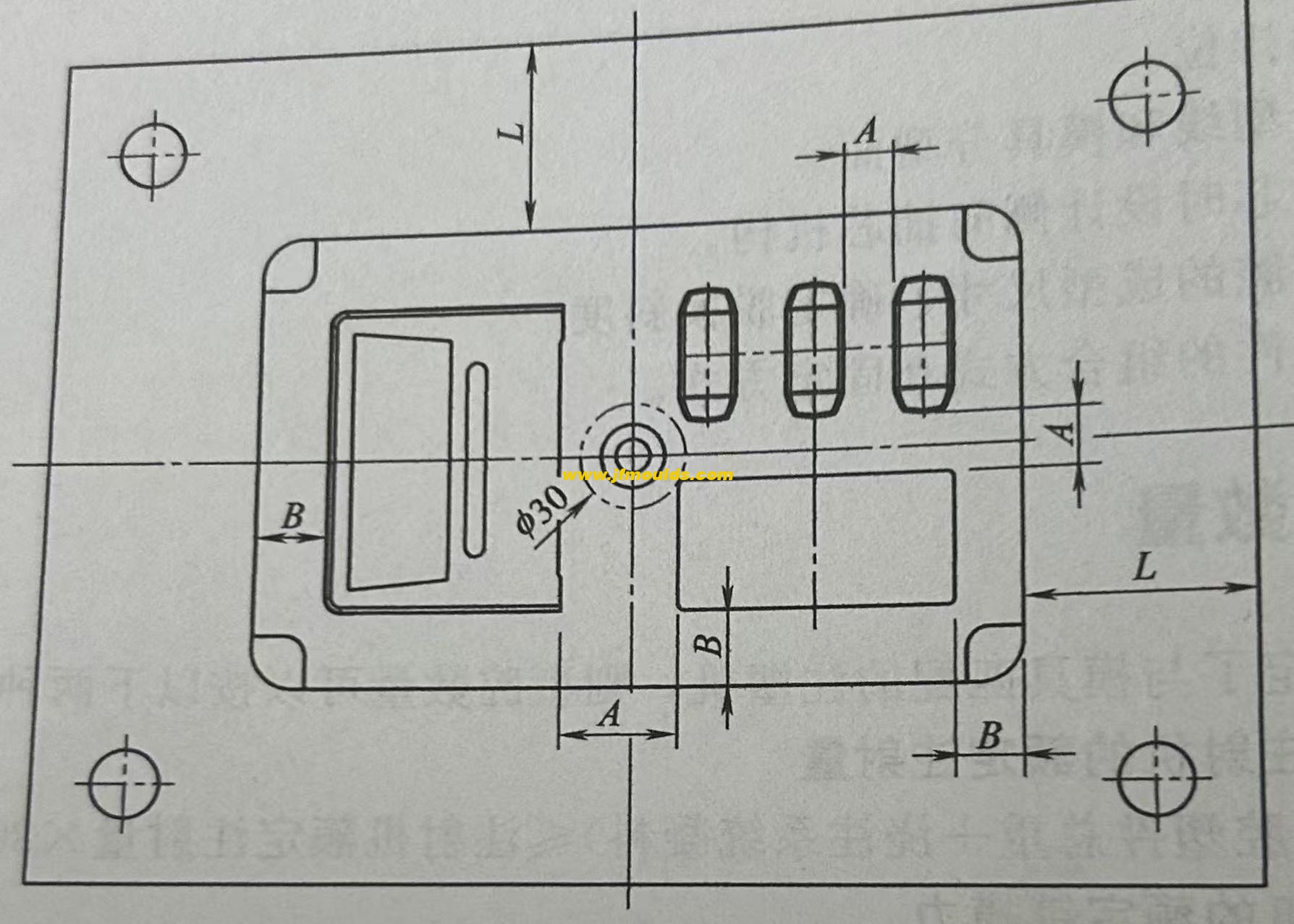
Las piezas de plástico más grandes o más complejas deben colocarse cerca del corredor principal, es decir, el manguito de la puerta. Sin embargo, la cavidad no debe estar dispuesta dentro de un diámetro de 30 mm alrededor del manguito de la compuerta tanto como sea posible, o el espesor del acero desde la cavidad hasta el manguito de la compuerta debe ser de al menos 8 mm.
Para moldes con múltiples cavidades en un molde, el espesor de acero A entre cada cavidad y el espesor de acero B desde la cavidad hasta el borde del inserto interior del molde se pueden seleccionar en función de la profundidad de la cavidad. Cuanto más profunda sea la cavidad, mayor debe ser el espesor del acero.
Special circumstances include:
When a concealed gate is used, there should be sufficient space for the concealed gate and the position for arranging the push rods
b. When the plastic part is large in size and the cavity is deep (60mm)
c. The size of the plastic part is relatively large, and the inner model core is inlaid through. At this point, the insert forms a frame structure 1 with poor rigidity. The steel thickness should be increased to enhance rigidity.
When cooling water needs to be passed between the cavities, the distance between the cavities should be larger to ensure that the steel thickness between the cavities and the cooling water channels is no less than twice the diameter of the water channels.
Sure enough, when the mold needs to be core-pulled from the side, the sequence should give priority to core-pulling from the left and right sides, and try to avoid core-pulling up and down.

Two: Parting surface
The main contents of parting surface design
The main contents of parting surface design are as follows.
① Position of the parting surface: Which part is formed by the moving mold and which part is formed by the fixed mold.
② Shape of the parting surface: Is it a plane, an inclined surface, a stepped surface or an arc surface
③ Positioning of the parting surface: How to ensure the positional accuracy of the core and cavity, and ultimately guarantee the dimensional accuracy of the plastic part
2. General principles for the design of parting surface positions
(1) The principle of aesthetic appearance
The selection of the parting surface should minimize its impact on the appearance of the plastic part. Especially for plastic parts with clear requirements for appearance, more attention should be paid to the influence of the parting surface on the appearance
(2) The principle of convenient processing
The selection of the parting surface should make the mold structure simple and easy to process, especially for the processing of the core and cavity.
(3) The principle of easy molding
The selection of the parting surface should be conducive to the pouring of the melt, the venting of the cavity and the design of the cooling system. Usually, when designing the parting surface, designers often encounter problems where there are more than two demolding directions on the plastic part.
For the shorter stroke demolding direction, the slider is used for lateral core-pulling. However, when the lateral core-pulling mechanism closes the mold, the clamping force it can provide is relatively small. If the projected area of the plastic part in this direction is large, problems will occur. For molds with inserts, the simplicity and convenience of insert installation should also be taken into consideration.
(4) Smooth demolding principle
The selection of the parting surface is conducive to the demolding of the plastic part, ensuring that the plastic part remains on the side with the ejection mechanism during mold opening (sometimes it is.
(Moving mold, sometimes fixed mold.)

Three: Shape design of the parting surface
The shape of the parting surface is best when it is a plane perpendicular to the mold opening direction, followed by inclined surfaces, then smooth arcs, stepped surfaces, etc. The parting surface shall not have sharp corners or edges. Sharp corners and edges will make processing more difficult and also affect the sealing material of the parting surface and the service life of the mold.
(1) Step parting surface
There are multiple options for the parting surface of this plastic part, and the final choice often depends on the customer's requirements.
(2) Inclined parting surface
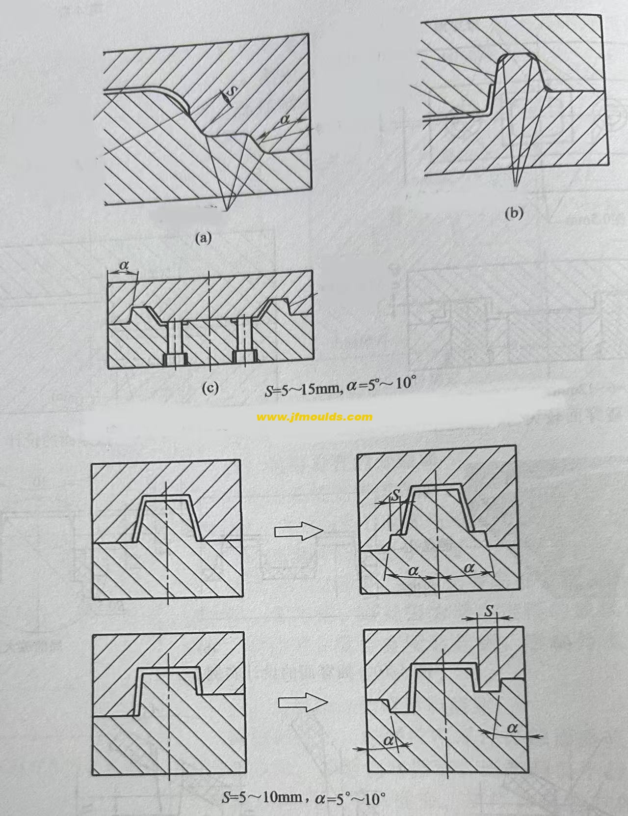
The inclined parting surface should be equipped with a stop mouth positioning surface to counteract the horizontal component of the expansion force. The positioning surface is determined based on the actual situation and can be on either side. Both (a) and (b) are acceptable. The inclination Angle of the positioning surface. It is generally 10 "to 15". The greater the slope, the worse the positioning effect. The inclined parting surface should extend outward by 5 to 10mm according to the Angle of the parting surface to prevent the edge of the cavity from cracking and to avoid movement during the FIT mold.
(3) Curved surface parting surface
The design of the curved surface parting surface is roughly the same as that of the inclined surface parting surface. In the figure, A=5 to 10mm, and the inclination Angle ea is generally 10 to 15°
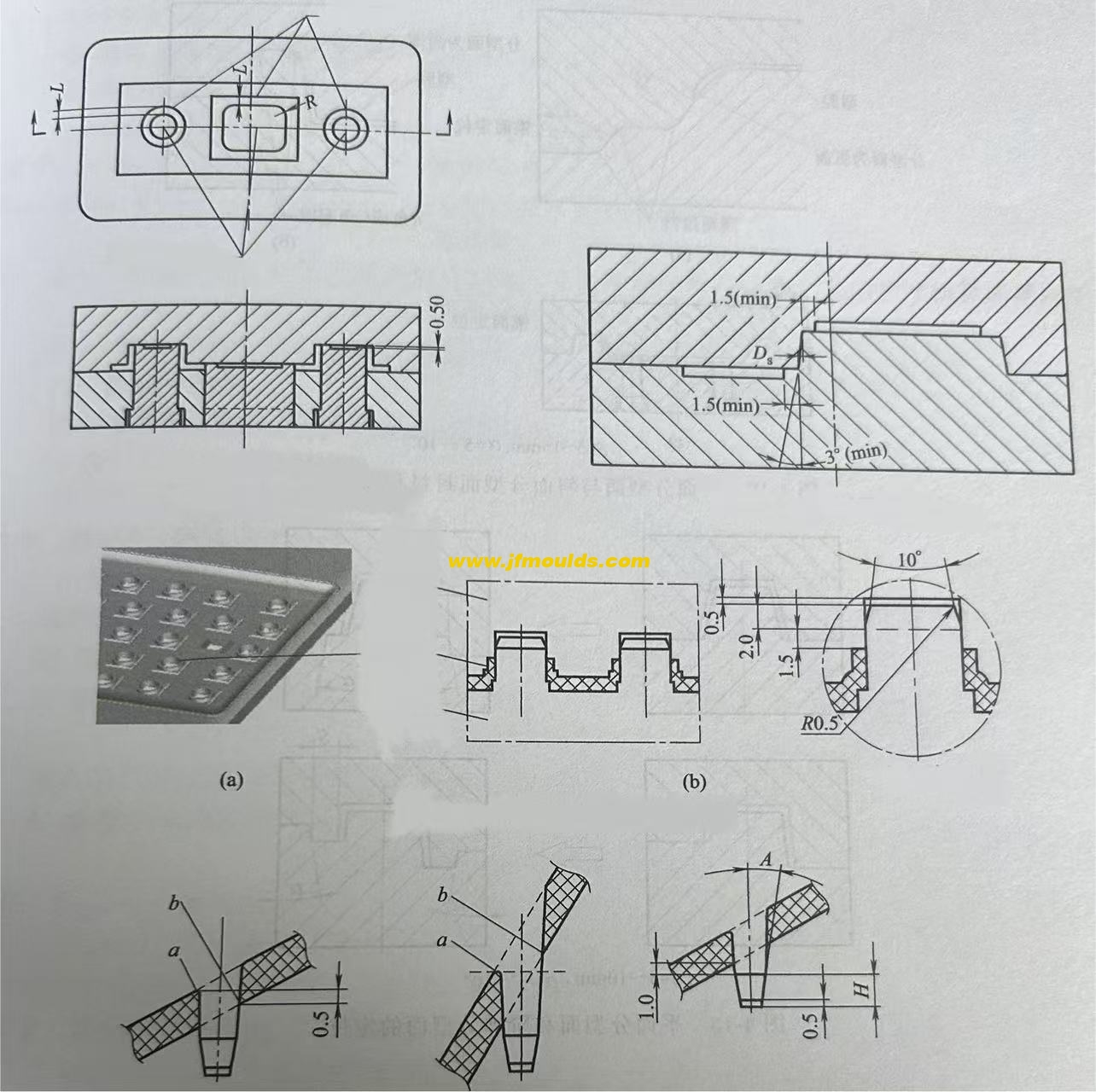
(4) The parting surface that is rubbed through or bumped through on the side
If the threading as shown in Figure 4-5(b) is adopted, the formed plastic part has no wire clamping, as shown in Figure 4-5(d), but the plastic part is prone to flash, and the flash is balanced with the side hole, reducing the size of the hole. When rubbing through, it is best to have a slope of 3 or more on the side. If the piercing method is adopted, the plastic part can see the wire clamping, but it is not easy to have flash. Even if there is flash and it is perpendicular to the hole, it does not affect the size of the hole. a is taken as 6°-10°. If c is chosen, it can be suggested that the customer make a slope of 3° to 5° on each side of the bump hole, so that there will be no wire clamping.
(5) The parting surface of the inclined square hole
The inclined square hole should be given priority for penetration. The condition for penetration is that if a<1° in the figure, the lateral core-pulling a 3° should be given priority.
(6) There is a raised parting surface on the side
There is a raised structure on the side. The parting surface should be prioritized for lifting, but this will cause wire clamping. Moreover, since the draft angles of the moving and fixed molds are exactly opposite, the wire clamping on both sides will have obvious lifting, affecting the appearance. If the customer cannot accept it, only lateral core-pulling can be adopted.
(7) Piercing and rubbing through on the parting surface
"Piercing through" refers to the contact surface of the moving and fixed mold forming parts being perpendicular to or roughly perpendicular to the mold opening direction; otherwise, it is called "rubbing through". When the contact surface is parallel to or approximately parallel to the mold opening direction, it is also called penetration. From the perspective of the convenience of mold manufacturing, the sealing surface on the parting surface should be pierced by impact as much as possible to avoid being rubbed through. Except for round holes which can be pierced by insertion, insertion is generally prohibited for non-round holes. When there are large through holes on the plastic part and the impact penetration surface on the mold is large, the middle of the impact penetration surface should be left empty to reduce the impact penetration area and facilitate the FIT mold.
Molde Co.,Ltd. de Taizhou Jiefeng de Mould_Taizhou de la materia (jfmoulds.com)
Four: Positioning of the parting surface
The guide pins and guide sleeves of the moving and fixed molds are clearance fits. They mainly serve to guide. The positional accuracy of the formed parts must be guaranteed during the design of the parting surface. If the plastic part is complex and the parting surface is inclined or curved, the shape and size of the sealing surface, how to position it, and there must be a measurement reference when designing the parting surface must be taken into consideration.
Even for planar parting surfaces or stepped parting surfaces, in order to improve accuracy, conical surface positioning is sometimes designed on the parting surface.

Información relacionada
Clasificación de moldes de inyección
2025-09-06
Clasificación de moldes de inyección Los tipos diferentes de moldes tienen diferentes necesidades ...
Los métodos decisivos para la altura de la posición de salida de agua al lado de la carcasa del molde, el daño y la deformación de la cavidad del moho delantero
2025-08-28
Los métodos decisivos para la altura de la posición de salida de agua al lado del molde ...
Verifique el grosor de la pared
2025-09-17
Verifique el grosor de la pared los principios para diseñar el grosor de la pared o ...
Desde el desarrollo personalizado hasta el suministro global, desbloquee la fuerza impulsora central de la fabricación moderna
2025-07-19
Desde el desarrollo personalizado hasta el suministro global, desbloquee la fuerza impulsora central de moder...
Centrarse en la calidad y cultivar profundamente la innovación
2025-07-05
Centrarse en la calidad y profundamente cultivar la innovación en la vida cotidiana, desde el mobi...
Las causas y soluciones de rayas de plata, decoloración, ondas de superficie y rugosidad en productos moldeados por inyección
2025-07-30
Las causas y soluciones de rayas de plata, decoloración, ondas de superficie y r ...


