Moho multi-componente
Moho multi-componente
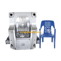
En la producción de moldeo por inyección de múltiples componentes (también conocido como moldeo por inyección multicolor-nota del traductor), se utilizan diferentes plásticos o plásticos de diferentes colores para producir productos moldeados por inyección a través de diferentes procesos.
En los últimos años, con la expansión continua de los campos de aplicación, la tecnología de moldeo por inyección de múltiples componentes se ha vuelto cada vez más importante. Las soluciones innovadoras en constante cambio hacen que el moldeo por inyección de múltiples componentes sea cada vez más atractivo en el mercado en crecimiento.
Una de las principales razones del rápido crecimiento de la tecnología múltiple es los beneficios potenciales que se obtienen al reducir los pasos de producción. Al aplicar la tecnología avanzada de moho, los procesos de ensamblaje manuales y automatizados de productos se pueden completar dentro de los moldes. Desde la perspectiva del diseño del producto, la tecnología de moldeo por inyección de múltiples componentes es atractiva para prevenir la piratería de diseño y los subproductos de dotación de subproductos con mejores efectos táctiles.
1. Tecnología Slider (Tecnología de retracción central)
La mayor ventaja de este proceso radica en la selección flexible de la posición de la entrada del segundo componente. Solo cuando se retira el control deslizante en la cavidad de la parte preplasticizada (es decir, el primer componente de plástico-nota del traductor) puede el segundo componente de plástico ingresar el espacio liberado en la parte preplasticizada.
Al usar la tecnología de retracción central, los productos estrechamente conectados se pueden producir con combinaciones de material compatibles. Es decir, antes de que se cura el primer componente, se inyecta el segundo material componente, y el molde no necesita moverse o abrir.
Debido a la conexión rápida durante el proceso de moldeo por inyección, la conexión entre los dos componentes en el producto es muy uniforme, mientras que el segundo componente se logra el verdadero enclavamiento de la forma geométrica. En el estado fundido, el segundo componente del plástico puede filtrarse fácilmente en los espacios del primer componente. Esta tecnología es simple y ahorrador de espacio.
Debido a que no se puede lograr el moldeo por inyección paralelo en el proceso de retracción del núcleo, los tiempos de moldeo por inyección de los dos materiales se superponen. El moldeo de inyección secuencial de diferentes componentes aumenta el ciclo de moldeo total. Debido a este inconveniente, el método de reversión central se ha utilizado cada vez menos.
2. Proceso de moldeo por inyección de transferencia (transferencia de mano mecánica)
El moldeo por inyección de transferencia se usa cuando las piezas moldeadas por inyección deben ser superadas. Las posiciones para el moldeo previo a la inyección y el moldeo de inyección final se pueden organizar a la izquierda y a la derecha o hacia arriba y hacia abajo. La mano mecánica transfiere las piezas preplásticas y agarra los productos terminados.
Similar al proceso de retracción del núcleo, este tipo de molde no requiere acción de rotación, por lo que su estructura no es complicada. Su ventaja es que los dos materiales se pueden moldear por inyección simultáneamente. En comparación con el método de retracción central, acortará en gran medida el ciclo de moldeo.
El proceso de moldeo por inyección de transferencia también incluye: moldeo previo a la inyección de un determinado producto en una máquina, luego eliminando esta parte pre-moldeada y completando el moldeo por inyección con otro material en otra máquina.
La confiabilidad del proceso de incrustar partes prelásticas en otra cavidad es extremadamente crucial. El proceso de ajustar la mano mecánica basada en la experiencia es bastante complicado. Se necesita un dispositivo de mano mecánico preciso y controlable para garantizar el posicionamiento preciso de las piezas preplásticas en la estación final.
El proceso de moldeo por inyección de transferencia hace que el área del panel de moho existente, pero no es adecuado para producir piezas moldeadas por inyección con geometrías muy finas.
Molde Co.,Ltd. de Taizhou Jiefeng del coche (jfmoulds.com)
3. Molma de placa de división
La placa divisoria está integrada en la plantilla de mudanza y puede girar. Después de que se abre el molde, la placa divisoria transfiere la parte prefirida a la siguiente estación del molde, y el producto final se moldea la inyección.
Se agregó una tercera plantilla rotatable a las dos plantillas del molde de placa divisoria. Esta placa puede girar alrededor del eje central. La placa divisoria se expulsa primero y se libera del lado del troquel en movimiento, y luego gira alrededor del eje central hasta la segunda posición. El movimiento de rotación impulsado por el bastidor es impulsado por un motor hidráulico o un servomotor, y su precisión puede alcanzar decenas de micras.
Después de que la placa divisoria se eleva, gira y disminuye hacia atrás, el núcleo volverá a su posición original en el dado en movimiento. Luego, el molde se cierra y comienza el siguiente ciclo de moldeo por inyección. En la segunda estación, la parte preplástica está incrustada con otro componente del plástico.
La rotación de la placa divisoria puede ser de 2 × 180 ° o 3 × 120 °. La tercera estación a menudo se usa para enfriar o eliminar piezas moldeadas por inyección. Los corredores calientes se usan muy limitados en los moldes de placa divisoria.

4. Molde de soporte central
El sistema central de stent es similar a la tecnología de placa de indexación. La placa divisoria se puede simplificar en una placa de tira larga o una forma de cruz. El soporte central solo gira la parte moldeada por inyección a la siguiente estación sin girar ningún componente mecánico del molde. Las piezas moldeadas por inyección se fijan mediante núcleos extensibles, pasadores de eyector o trinquete durante la transferencia.
La placa divisoria discutida anteriormente se ha simplificado en un soporte central que gira con la parte moldeada por inyección y luego procede con moldeo por inyección. Los moldes de andamio central generalmente emplean sistemas de corredores calientes. Una ventaja de esto sobre el sistema de placa de indexación es que el peso propio del sistema giratorio es más pequeño, lo que le permite girar o balancearse rápidamente, reduciendo así significativamente el ciclo de formación del sistema.
El moldeo de las piezas moldeadas por inyección se puede lograr por el lado de la inyección o el lado de la expulsión. Se agarra por un núcleo telescópico durante el desplazamiento y luego se empuja de un agujero central.
5. Sistema de tocadiscos
Multi-component molds using turntable systems have been widely applied in various fields of the plastic industry. Depending on different application scenarios, the turntable can be driven by hydraulic power or a motor. Using a turntable system is the most effective solution for the mold to rotate from one injection position to the next. The rotation of the mold is accomplished by the turntable, making the mold simpler.
Depending on the number of injection molding components, the positioning of the turntable can be divided into 4×90°, 3X120° or 2X180°. Among them, the simplest is to rotate the turntable 180° to the left or right. The feature that the moving die can rotate continuously in one direction is particularly suitable for multi-station molds. As the mold needs to rotate continuously, cables and
The connection of hoses, the supply of cooling water and hydraulic oil will become quite complicated.
Compared with other multi-component molds, one drawback of the turntable system is that it requires a larger injection molding machine. Generally, the length of the machine guide rails in a turntable system needs to be increased by 200mm, and the distance between the guide rails needs to be increased by 50 to 100mm.
6.bucket lifting mold
In a broad sense, the working mode of bucket lift molds and transfer injection molding technology is similar. The production is transferred from an integrated screw mechanism to the next injection molding station.
The highlight of this mold technology is that the multi-component injection molding machine used does not require special specifications. The mold will be slightly longer than the rotating mold, but it doesn't need to be rotated. In this way, there is no need to enlarge the template or increase the length of the guide pins of the injection molding machine.
The pre-molded part is moved to the next station through a screw. Then, the product undergoes injection molding and is transferred to the unloading station outside the mold. The mechanical hand takes down the finished product during the injection molding stage, and the injection molding cycle will not be affected.
The empty half mold is sent back to the injection molding station again. During the mold opening stage, the second screw moves the half mold from the unloading station to the pre-plasticizing station. In this way, the bucket lifting cycle is completed and a new cycle begins anew.
Molde Co.,Ltd. de Taizhou Jiefeng de Mould_Taizhou de la materia (jfmoulds.com)
7-cubic-meter stacked mold technology
The advantage of cubic mold stacking technology over other mold technologies lies in the fact that with the same size of machine, the number of cavities in the mold can be doubled. In other words, for the same order volume, the size of the machine can almost be halved.
7.1 Cubic rotary mold stacking technology
When applying the rotary die stacking technology, the rotation of the mold is accomplished by a horizontally rotatable central module.
The pre-plastic part is first formed on the first parting surface. When the mold is opened, the pre-plastic part remains on the central rotating module. When the mold is fully opened, the central module rotates 180° to the second profile surface. After the mold is closed again, the second component of the plastic is injected into the second cavity containing the pre-molded part.
By applying a 4×90° rotating cubic die, secondary processing can be carried out simultaneously at the second station (operator side) and the fourth station (non-operator side). For instance, the second station is used for cooling injection-molded parts, while the fourth station is for the mechanical hand to pick up the products. The two processes are carried out simultaneously without affecting the molding cycle
Impact. Alternatively, the second station can also be used for in-machine or out-of-machine assembly (in-mold assembly).
7.2 Double Cubic rotating Die Stacking Technology
The double cubic stacked mold is placed between the moving and fixed half molds, and two sets of rotating stacked molds are also configured. In principle, a double-cubic stacked mold is like two independent molds working simultaneously. It has three clamping surfaces and all forming processes are carried out simultaneously, which makes the production of complex parts highly efficient.
Compared with traditional molds, when the assembly process needs to be transferred to the mold, the double cubic stack mold has a significant advantage, and the molding cycle will also be greatly reduced. Assembly processing can be carried out simultaneously with injection molding. More and more assembly processes have been transferred to in-mold operation. Because the products assembled in the mold have higher precision.
The preferred application fields of double cubic stacked molds include packaging, medical care and the automotive industry. With one process, the integration of two or more packaging components can be achieved.
8. Sequential mold stacking
Sequential mold stacking involves two sets of molds being connected back to back, with plastic filling each mold cavity in sequence and the molds being opened in a cycle.
In a common mold, the cavities on the parting surface stand opposite to each other. They are filled simultaneously during each injection molding, and the finished products are demolded at the same time when the mold is opened.
However, in sequential die stacking, the parting surfaces open alternately. That is to say, when half of the mold cools down, the other half of the mold is just demolded and re-injected. During the idle time of mold cooling, the next injection molding stage can be carried out. When the two semi-molds work in sequence, different injection molded parts of the same product series can be produced. Therefore, injection molding machines must be equipped with special programs to provide the appropriate amount of plastic required for each parting surface.
Thick-walled parts with longer cooling times are also particularly suitable for this technology.
The external edge lock mechanism enables the two semi-molds to operate alternately. The function of the side lock is similar to that of a rack and pinion system. By using a single adapter board, two ready-made molds can be transformed into a set of sequential stacked molds.
9.component molds for thermosetting plastics and elastomers
In thermosetting multi-component molds, thermosetting plastics are rarely paired with thermosetting plastics. In most cases, two types of materials, soft and hard, are used in combination. However, there are also examples of combinations of thermosetting plastics and high-temperature resistant thermoplastic central support rotary process indexing sheet materials.
Elastomers can be combined with thermoplastics and thermosetting plastics. In both cases, the pre-molded parts should be made of hard plastic.
The combination of thermosetting plastics and elastomers is mostly used in the field of engines. Both of these plastics have the characteristics of good thermal stability, resistance to engine oil and fuel oil. Therefore, thermosetting plastics and elastomers [usually nitrile rubber (NBR)] with very similar material classifications can be combined very well. The temperatures at which these two materials are produced using heated molds are also at the same level. The difference between them lies in that thermosetting plastics need to be hardened to become elastic
The body needs to be vulcanized.
The combination of soft and hard plastics can be used to improve the sense of touch or absorb vibrations. Examples of improving tactile sensation through the combination of soft and hard plastics include small devices such as hand drills, welding guns or hair dryers. Such a combination can be used in automotive engineering and engine technology to selectively absorb vibrations.
Información relacionada
Definir un nuevo paradigma para la industria del molde de inyección a través de avances tecnológicos y reconstrucción ecológica
2025-07-04
Definir un nuevo paradigma para la industria del molde de inyección a través de...
Centrarse en la calidad y cultivar profundamente la innovación
2025-07-05
Centrarse en la calidad y profundamente cultivar la innovación en la vida cotidiana, desde el mobi...
De los avances tecnológicos a la transformación inteligente
2025-07-07
De los avances tecnológicos a la transformación inteligente...
Molde de inyección: el "Creador invisible" en el taller
2025-07-09
Molde de inyección: El "Creador invisible" en el workshopI. La primera impresión de la...
Proceso de procesamiento de diseño de fabricación de moldes
2025-06-19
El flujo del proceso de 1. fabricación de moldes es el siguiente: revisión de dibujo-material...
De principio a aplicación, entender este "maestro de conformación" en la industria
2025-07-16
Desde el principio hasta la aplicación, comprenda este "maestro de conformación" en la industria P...